Thanks to AI making any kind of programming very accessible, I decided to try my hand at automating certain things in my home. I’ll publish a series of articles which share my learnings as I make progress with the project.
The Use Case
We have a couple of overhead water tanks which supply water throughout the house. The challenge we have at the moment is our lack of awareness of the water level in these tanks. We will only get to know that a tank is empty when water stops running through the taps — the event that requires turning on a motor to refill the tanks. And after this, we usually detect that the tank is full only when the tank starts overflowing and we see water running waste into the drain. There are simple solutions to these problems available in the form of buzzers or what not but I wanted to pick this use case to begin the home automation journey. I want to eventually get to a point where the water motor that fills up the tank should switch on and off autonomously depending on the water level.
Approach
Instead of picking up and solving the entire problem at once, I picked a smaller MVP to be addressed first. This should help me do both a feasibility check that the system would work and also give me confidence that I can do this. So, two primary questions need answers.
- How to detect the level of water in the tank?
- Once I detect this, how do I publish that data?
I decided to worry about all the other problems later. So this article would only talk about these two. The rest of the setup will be covered in follow-up articles in this series.
How to detect the level of water?
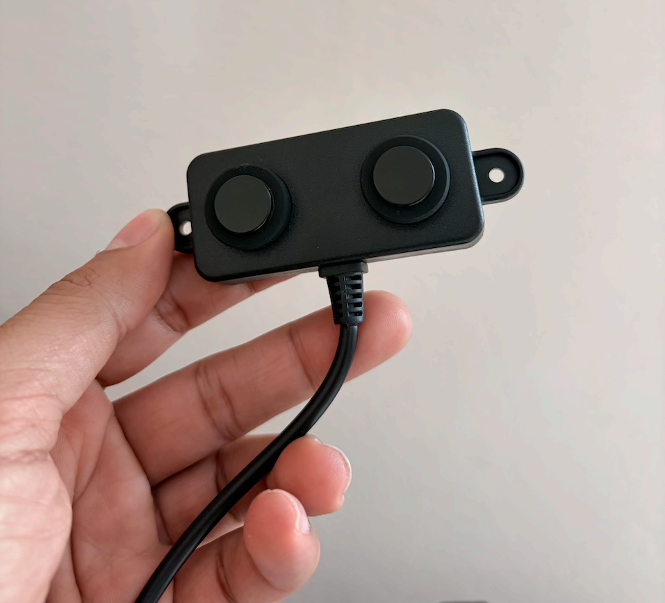 Water is solid to sound. To sound waves it is yet another medium from which they end up bouncing off. Lot of sensors are built around this fundamental that sound waves can bounce back when they meet water. So the answer to our first question is an Ultrasonic sensor.
There are various ultrasonic sensors available with varying degrees of cost and their corresponding quality.
The following are a few models I found
- HC-SR04 Ultrasonic Distance Sensor - Not water proof.
- Waterproof Ultrasonic Sensor - Water proof but not humidity and dust proof.
- A02YYUW Waterproof Ultrasonic Sensor - Better choice.
Amongst the three, A02YYUW module turned out to be a good fit as I was planning to install it on the overhead tank and it is prone to rain, dust and humidity from the water within the tank itself. I purchased one from a local electronics market in Hyderabad for Rs. 1850/-.
How to publish the data from the sensor?
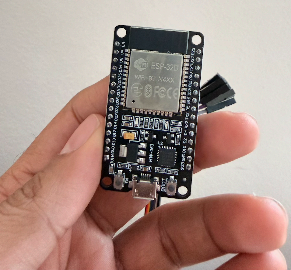 I needed a small microcontroller board which can do two things, connect to the sensor to read the water level and connect to WiFi to transmit the sensor data read. This can be achieved either using an Arduino board or an ESP32. An ESP32 is a better choice here as it has better performance and is widely used with the IoT ecosystem.
So, along with the Ultrasonic Sensor, I purchased an ESP32-WROOM-32 Devkit for Rs.240/- from the same electronics store. I also purchased a few jumper cables of all combinations (male-male, male-female and female-male) to connect easily.
The Voltage problem
Another reason, that I did not call out earlier, for going with A02YYUW sensor is its operating voltage. While researching, I found out that GPIO pins of ESP32 expect to receive 3.3V, whereas the other ultrasonic sensor modules transmit 5V. This would be harmful to the ESP32. If we use a sensor that transmits 5V, we would have to build a voltage step-down converter.
The Implementation
So the final setup is going to be an ultrasonic sensor connected to ESP32, which is in turn connected to WIFI. For this iteration, I limited the setup to just connect to WIFI rather than transmitting the reading over WiFi. So I will tether to ESP32 module and see if I am able to read the data in development mode.
Here’s how the physical pieces sit relative to each other for this iteration:
%% float-right
flowchart TB
    subgraph Tank["Overhead Water Tank"]
        Sensor["A02YYUW\nUltrasonic Sensor"]
    end

    subgraph Board["ESP32-WROOM-32 Devkit"]
        UART["UART RX · GPIO16\n9600 baud"]
        Firmware["ESPHome firmware"]
    end

    subgraph Laptop["Development Mac"]
        CLI["esphome CLI"]
    end

    subgraph LAN["Home WiFi Network"]
        Router["Router"]
    end

    Sensor -->|"4-byte frame · 3.3V"| UART
    UART --> Firmware
    Laptop -->|"USB tether\npower + flash + logs"| Board
    Firmware -.->|"WiFi (connectivity only,\nno publish yet)"| Router
The Hardware Setup
As I am not going to do the full installation of the sensor with this iteration itself, the only hardware setup needed is
- Properly connect the A02YYUW sensor to ESP32.
- Connect my Mac and ESP32 with a MicroUSB Cable. This will work as both power supply and a data tether for flashing the ESP32 module.
Connections between Ultrasonic Sensor and ESP32
I have an ESP32 module which has DXX labelled pins. The A02YYUW has a 4-pin JST connector. This is how I connected the ESP32 and the A02YYUW sensor
| ESP32 Pin | A02YYUW Pin | What for? |
|---|---|---|
| VIN | 1 | Voltage Input to the sensor |
| GND | 2 | Ground/Voltage output |
| RX2 | 4 | Signal Receiver |
I didn’t connect anything to the Transmit pin (TX2) as we are only reading data from the sensor. I then found an old MicroUSB cable and connected the ESP32 to my laptop.
The Software Setup
This is the interesting bit. The next task is to flash the ESP32 with the functionality we want: Connect to WiFi and Connect to A02YYUW. This can either be done using bare bones C/C++ or using multiple frameworks that are available out there. While researching for the right framework, I came across ESPHome (https://github.com/esphome/esphome). It is a framework that supports flashing the ESP32 using a configuration file. We don’t have to write the daunting C/C++ code. ESPHome also supports integration with Home Assistant which we will talk about in a future article.
I installed ESPHome locally and had AI prepare this configuration file. I’ve trimmed the comments down here — the interesting bits are explained below the code instead.
esphome:
  name: overhead-tank-monitor
  friendly_name: "Overhead Tank Monitor"

esp32:
  board: esp32dev  # ESP32-WROOM-32 / ESP-32D
  framework:
    type: arduino

wifi:
  ssid: !secret wifi_ssid
  password: !secret wifi_password
  ap:
    ssid: "Overhead-Tank-Monitor Fallback"
    password: !secret ap_fallback_password

captive_portal:
logger:
api: {}

ota:
  - platform: esphome

uart:
  - id: uart_tank1
    rx_pin: GPIO16
    baud_rate: 9600

interval:
  - interval: 50ms
    then:
      - lambda: |-
          static uint8_t buf[4];
          static uint8_t len = 0;
          static uint32_t last_publish = 0;
          const uint32_t PUBLISH_PERIOD_MS = 3000;  // a tank's level doesn't change fast; matches level-% update_interval
          while (id(uart_tank1).available()) {
            uint8_t data;
            id(uart_tank1).read_byte(&data);
            if (len == 0 && data != 0xFF)
              continue;
            buf[len++] = data;
            if (len == 4) {
              uint8_t checksum = buf[0] + buf[1] + buf[2];
              uint32_t now = millis();
              if (buf[3] == checksum && now - last_publish >= PUBLISH_PERIOD_MS) {
                last_publish = now;
                uint16_t distance = (uint16_t(buf[1]) << 8) | buf[2];
                ESP_LOGI("tank1", "Distance: %u mm", distance);
                id(tank1_raw_distance).publish_state(distance);
              }
              len = 0;
            }
          }

sensor:
  - platform: template
    name: "Tank 1 Raw Distance"
    id: tank1_raw_distance
    unit_of_measurement: "mm"
    accuracy_decimals: 0

  - platform: template
    name: "Tank 1 Water Level"
    id: tank1_level_pct
    unit_of_measurement: "%"
    accuracy_decimals: 0
    update_interval: 30s
    lambda: |-
      const float SENSOR_TO_EMPTY_MM = 2000.0;
      const float SENSOR_TO_FULL_MM  = 200.0;
      if (isnan(id(tank1_raw_distance).state)) {
        ESP_LOGI("tank1_pct", "raw distance not yet available (NaN)");
        return {};
      }
      float raw = id(tank1_raw_distance).state;
      float pct = (SENSOR_TO_EMPTY_MM - raw) / (SENSOR_TO_EMPTY_MM - SENSOR_TO_FULL_MM) * 100.0;
      if (pct < 0) pct = 0;
      if (pct > 100) pct = 100;
      ESP_LOGI("tank1_pct", "raw=%.0f mm -> level=%.1f %%", raw, pct);
      return pct;
A few things worth calling out about that config that didn’t fit in a comment:
- The UART parser in the
interval:block is hand-rolled, not ESPHome’s built-injsn_sr04tcomponent. I tried the built-in component first and it produced nothing — no valid readings, no blind-zone warnings, zero output — across repeated tests, including direct-to-Mac power and 30+ seconds of continuous hand-sweep motion. The exact same UART byte stream, read manually with a parser matching the sensor’s 0xFF-header/high-byte/low-byte/checksum frame format, read reliably the whole time. So that hand-rolled parser is now the permanent driver for this sensor. - Only Tank 1 is wired up. Tank 2 gets its own
uart:entry once the second A02YYUW is mounted. - MQTT is left out entirely for now — Mosquitto isn’t running yet, so there’s nothing to publish to. Both of these, along with the Home Assistant integration, are for a future article.
SENSOR_TO_EMPTY_MMandSENSOR_TO_FULL_MMare still placeholders. They need calibrating against the real tank once it’s mounted.
Flashing the ESP32
The command to run to flash the ESP32 module is this
esphome logs esphome/tank-monitor.yaml --device /dev/cu.usbserial-0001You will have to identify the device identifier of the ESP32 connected through USB and provide that as the --device argument. The following command on macOS provides the files of devices connected through USB.
ls /dev/cu.usbserial*This will only have to be done one time. After we flash ESPHome for the first time, we can then flash it OTA using WiFi. If you notice, the configuration YAML contains the following entry to support that
ota:
  - platform: esphome
So, after the first flash, the following command reflashes the ESP32 over WiFi with any updates to the configuration YAML.
esphome run esphome/overhead-tank-monitor.yaml --device overhead-tank-monitor.localThe Test
You should be able to see the logs by running
esphome logs esphome/overhead-tank-monitor.yaml --device overhead-tank-monitor.localIf you are not able to connect using the hostname, first try connecting to it through the USB tether.
A successful WiFi connection would produce the following logs
[16:20:42.852][C][wifi:1553]: WiFi:
[16:20:42.852][C][wifi:1553]:   Local MAC: 8C:94:DF:72:47:34
[16:20:42.852][C][wifi:1553]:   Connected: YES
[16:20:42.852][C][wifi:1259]:   IP Address: 192.168.68.114
[16:20:42.852][C][wifi:1270]:   SSID: 'Gyandus'
[16:20:42.852][C][wifi:1270]:   BSSID: 6C:5A:B0:C9:E5:1A
[16:20:42.852][C][wifi:1270]:   Hostname: 'overhead-tank-monitor'
[16:20:42.852][C][wifi:1270]:   Signal strength: -58 dB ▂▄▆█
[16:20:42.852][C][wifi:1270]:   Channel: 4
[16:20:42.852][C][wifi:1270]:   Subnet: 255.255.255.0
[16:20:42.852][C][wifi:1270]:   Gateway: 192.168.68.1
[16:20:42.852][C][wifi:1270]:   DNS1: 49.205.171.194
[16:20:42.852][C][wifi:1270]:   DNS2: 49.207.34.210
And the Ultrasonic sensor should produce the following log entries if everything is successful.
[16:22:42.685][I][tank1_pct:111]: raw=2643 mm -> level=0.0 %
[16:22:42.787][S][sensor]: 'Tank 1 Water Level' >> 0 %
[16:22:43.684][I][tank1:076]: Distance: 2643 mm
[16:22:43.793][S][sensor]: 'Tank 1 Raw Distance' >> 2643 mm
[16:22:45.690][I][tank1_pct:111]: raw=2643 mm -> level=0.0 %
[16:22:45.800][S][sensor]: 'Tank 1 Water Level' >> 0 %
[16:22:46.733][I][tank1:076]: Distance: 379 mm
[16:22:46.836][S][sensor]: 'Tank 1 Raw Distance' >> 379 mm
[16:22:48.688][I][tank1_pct:111]: raw=379 mm -> level=90.1 %
[16:22:48.800][S][sensor]: 'Tank 1 Water Level' >> 90 %
[16:22:49.762][I][tank1:076]: Distance: 377 mm
[16:22:49.837][S][sensor]: 'Tank 1 Raw Distance' >> 377 mm
[16:22:51.692][I][tank1_pct:111]: raw=377 mm -> level=90.2 %
[16:22:51.797][S][sensor]: 'Tank 1 Water Level' >> 90 %
[16:22:52.806][I][tank1:076]: Distance: 269 mm
[16:22:52.898][S][sensor]: 'Tank 1 Raw Distance' >> 269 mm
[16:22:54.689][I][tank1_pct:111]: raw=269 mm -> level=96.2 %
[16:22:54.794][S][sensor]: 'Tank 1 Water Level' >> 96 %
[16:22:55.834][I][tank1:076]: Distance: 262 mm
[16:22:55.948][S][sensor]: 'Tank 1 Raw Distance' >> 262 mm
The distance is tested using my own hand as an obstacle. That should be it for now — we have evidence that the setup works. Time to move to the next step.
Continue to Part 2: Setting Up the Home Lab, where I bring up a Debian server running Home Assistant and ESPHome.